
Thrown Objects
From as early is 400,000 BC, humans have used more sophisticated thrown objects as weaponry. Evidence of humans using spears as early as this has been discovered (read this Nature article to find out more). Thrown objects evolved to become more precise and effective as technology evolved, and are the basis for much of the technology we explore on this site. This page, in particular, looks at what projectile motion is, and a few examples of early projectiles.
Information in these green boxes is considered advanced reading! Read this information if you want to learn more.
What would you like to read about?
What is projectile motion?

WHAT IS PROJECTILE MOTION
Projectile motion is defined as a type of motion in which an object or particle (aka, a projectile) is thrown close to the Earth's surface - and the only significant force defining its motion is Earth's gravity.
This video shows how to derive properties of projectile motion using first order kinematics, or SUVAT equations.
In short, by using the SUVAT equations,
in the horizontal and vertical planes, and using the gravity of the Earth (or g) as the downward acceleration, one can determine various dynamic properties of the projectiles. In these equations, s is the displacement, u the initial velocity, v the final velocity, a the acceleration and t the time of flight.
.
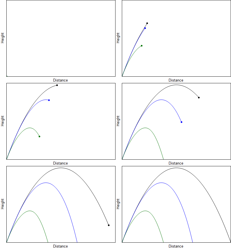
However, as we know, the case that only gravity acts on the particle is untrue in real life applications of projectiles. Air resistance and wind are some of the other forces that can act on a particle to alter it's trajectory, as demonstrated below.
These drag forces do work against the motion of the projectile, causing energy loss, and consequently limiting both the maximum height and the horizontal range of the projectile, and this must be accounted for when designing and estimating how to use weaponry that incorporate projectiles.
Three objects being thrown with the same angle of trajectory. The black projectile experiences no air resistance, the blue experiences Stoke's Drag, and the green, Newtonian Drag.
The type of drag that the projectile experiences depends on the Reynolds Number of the fluid (in this case, air) that the projectile is moving through. The number helps decide whether the path will be laminar (smooth) or turbulent (rough). The two types of drag demonstrated above are both for low Reynolds numbers (>1).
Let us explore one of these kinds of drag for a small projectile with a relatively low velocity. In this case, the Reynold’s number will be small, and so the flow will be laminar, and we use Stoke’s Law given that the inertial forces are negligible compared to the viscous forces (and under Newton’s drag, the converse is the case). The drag force in the case of Stoke’s Law was derived by George Gabriel Stokes, and was shown to be:
where b is the drag constant in the case of Stoke’s Law, r is the Stoke’s radius of the particle, and η is the fluid viscosity. Given that the equation for viscous resistance is
we get the following expression for Stoke’s Drag:
where Fd is the drag force and v is the velocity. There are other kinds of drag that can affect the path of an projectile, such as lift induced drag. Read more about the different kinds of drag here.
Understood to originate from Australia, boomerangs were used by Aborigines as a throwing club to hunt, and its use has since transformed from weaponry to a common toy. As some of the most interesting early projectiles, boomerangs are a great example to study in depth.
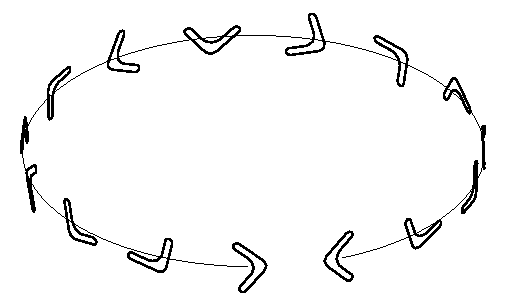
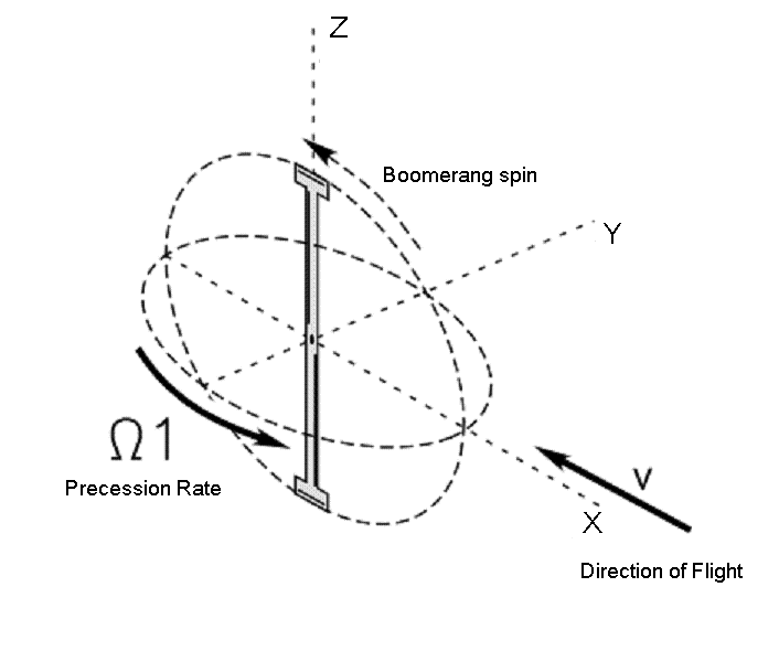
A boomerang is a classic example of a gyroscopic precession and it’s returning trajectory involves this and the aerodynamic lift of it’s aerofoil shape. The precession allows the aerofoil to fly along a returning path.
For the more traditional boomerang, the actual structure of the boomerang means that each end of it forms an aerofoil heading into the wind whilst it is at the top of the motion - meaning the lift force is always greater on the top of the spinning structure.
This design causes the boomerang to travel in the direction thrown - and the higher aerodynamic lift on the top end provides a torque, causing the angular momentum to precess and gradually moving the heading of the aerofoil in a curved path. To read more about aerofoils click here.
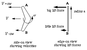
Let's consider the forces acting on a boomerang of radius a. The centre of the boomerang is travelling at a constant forward speed, which we will call V, and the boomerang is spinning with angular velocity as shown in the diagram below.
The top end is moving faster than the forward velocity, and the bottom end is moving slower with a velocity lower than the forward velocity. As a wing generates more lift when it moves faster, point A generates more lift than point B.
But why do boomerangs always seem to have a returning, almost circular path?
Let us consider a very simple answer to this question: The constant centripetal force F causes circular motion with the velocity v on a radius r such that
where m is the mass of the boomerang. So, we can consider a circular path, such as this one.

Information in these blue boxes is considered advanced reading! Read this information if you want to learn more, and click on links to read about concepts related to the information.
Information in these blue boxes is considered advanced reading! Read this information if you want to learn more, and click on links to read about concepts related to the information.
Now, let us consider a more advanced treatment of the boomerang. A constant couple force C acting on a gyroscope, which in this case is our boomerang, causes it to have a precession rate Ω where
where J is the moment of inertia of the boomerang and ω is its angular velocity.
If Ω corresponds to the angular velocity of the circular motion exactly, the boomerang will continue at the rate required for it to remain tangential to the flight path. This gives us an equation relation V to Ω:
The aerodynamic force involved in this, which we can call L, is generated due to a wing of area A travelling with velocity v in air of density ρ. The precise relationship between all these variables is expressed by something called the lift coefficient or CL, and it can be defined by the following:
Now, if we consider the case of a more rare cross-shaped boomerang, the net lift force F, and the aerodynamic couple C can be defined as the following:
From this, we show that the radius R of the circular flight path is independent of spin speed ω and forward velocity V, and that for a given boomerang it is a constant:
DID YOU KNOW? Using the above equations, you can determine the"flick of wrist" force required to get the boomerang to fly well. Give it a go!

The Boomerang

BOOMERANG
Information in these blue boxes is considered advanced reading! Read this information if you want to learn more, and click on links to read about concepts related to the information.
The Spear
We’re all aware of the javelin throw in sports - a graceful yet lethal instrument that originated from the spear. Spears have been used for centuries as a way to hunt, and for warfare, used by both the Mycenaean’s and the Romans. Lances, used by the cavalry and in jousting matches, were a modification of the spear: which originally is a thin pole weapon, usually made of wood, with a pointed head which acts as the offensive part of the weapon. The javelin - in fact - was designed as a lighter version of the spear, to target enemies further away before it was used as a regular instrument in sports.
The length and freedom to grip the weapon wherever you desire allows the reach of the weapon to be further than a traditional, ball-like projectile, and increases the leverage - increasing the damaging impact of the weapon. The diagram below demonstrates the basic forces acting on a spear.
There are numerous variables to be taken into consideration during a spear throw - and many of these, such as drag and gravity, are out of the thrower’s control. To begin with, then, let us consider the three core factors of the throw:
-
Speed of Release
-
Trajectory at Release
-
Height of Release
SPEED OF RELEASE:
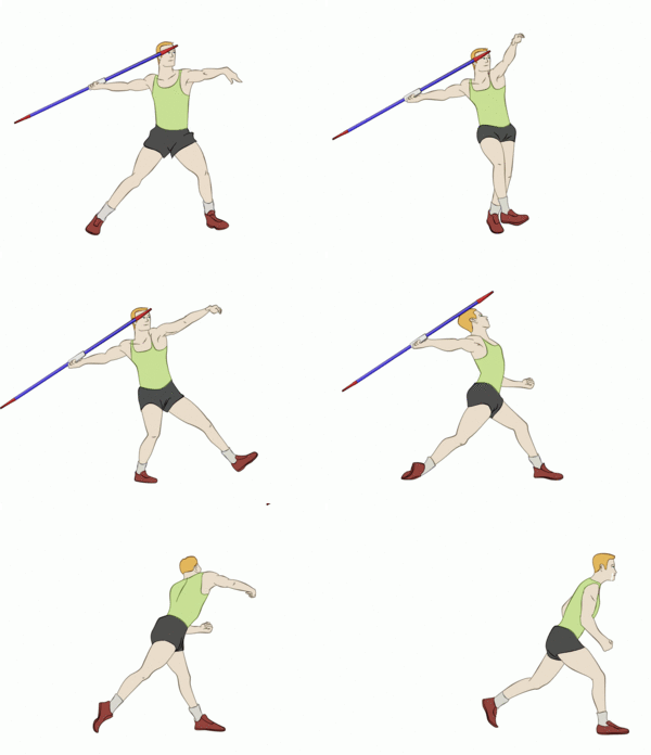
As spear-throw is almost always accompanied with a run-up. The reason for this is Newton’s First Law: “An object tends to maintain its current state of motion unless acted upon by an external force” - also known as inertia. A spear travels with the thrower at the same speed as their run, and the additional muscular force applied to the spear during the throw further increases the speed with which the spear will launch. That is, the velocity of the run and the velocity due to the throw simply add together to give the resultant velocity. This is of course a simplification, but for the purposes of understanding, we can use this as an approximation. Of course, at high speeds, the throwing technique might be compromised due to fatigue, but, as a general rule, the faster a thrower runs, the further the spear will travel.
Let us consider now consider Newton’s Second Law, that is:
where F is force, m is mass and a is acceleration. We can clearly say that the acceleration of the spear is directly related to the force the thrower exerts during the throwing motion of the spear, as the mass of the spear is constant. It is important to maximise the power in the throw by using trained throwing technique, maximising the power of each of the muscles involved, and in the case of the spear, this force is known as the thrust. We assume, for simplicity that this thrust is applied about the centre of gravity of the spear.
At a given instant, for a projectile moving with velocity v we can say that
So, at the instant that the thrower launches the spear, the speed at which the spear launches is directly related to the the amount of time the acceleration lasts. That is, the longer the spear is in the air, the faster it will be, meaning the impact will be greater, as demonstrated by
where Ft is the impact term, m is mass and Δv is the change in the velocity
The most effective throws would combine an understanding of these concepts but also would understand that for the resultant force to be maximised they must be in the same direction: the direction of the run and the throw must be as close to identical as possible.

SPEARS
TRAJECTORY AT RELEASE
It is important to note that the trajectory of motion refers to the angle of the centre of mass of the spear at release, and not the spear itself.
If there was no air resistance, the ideal launch angle would be 45°, as this angle would maximise the horizontal range for a given time in a projectile motion.
In a projectile motion, the maximum height reached is when the vertical velocity is equal to zero, that is
when
where Vy is the vertical velocity. For any given point, this can be written as:
where V0 is the initial velocity, and so using SUVAT equations, we reach the following:
Now, for the turning point in our projectile, Vy is zero, so we achieve this:
For the horizontal, with zero acceleration, we obtain
where xs is the displacement in x, hereby known as x which leads us to
By plugging equation A into equation B, we are led to
This is only half the range, as it is for the turning point. We double this to get
and using
we can show
Recall that the maximum value of occurs at 1, giving us, in turn
which is why 45° is considered optimum.


[Eq. A]
[Eq. B]
Introducing drag would mean that this value is reduced slightly. Why? The drag slows down the total velocity, so reducing the angle from the horizontal slightly allows the horizontal velocity to be favoured slightly, increasing it’s range.
The thrust applied by the thrower may determine the trajectory, but it is important to remember that this trajectory is also affected by the drag, which acts against the spear - and so javelin throwers in sport use lighter, thinner carbon based javelins to increase the range of their javelin.
HEIGHT OF RELEASE
Simply put, the higher the point from which the spear is launched, the further it will travel, for any given angle and initial velocity. This is due to the fact that the higher the the point of release, the greater the displacement, and the longer the spear will remain in the air. However, if the spear is launched without a high enough release velocity, this could compromise the distance covered by it, and the impact on it’s collision. The ideal throw would combine the optimum conditions for height, speed and trajectory to achieve the best throw.
The Trebuchet

TREBUCHET
Finally, one of the later thrown-object weapons, we briefly discuss trebuchets - in particular, counter-weight trebuchets. Largely as a siege weapon in the middle ages, trebuchets are based on the principle of energy conservation, and in this case, the two types of energy we are concerned with are potential and kinetic energy. It was also one of the first weapons to use a lever to maximise its output power.
A trebuchet throws objects by using the energy of a falling, hinged, counterweight to launch the payload - or the projectile - around a pivot, to achieve a high launch speed, which results in a greater range, as discussed in the spears section of this page.
The potential energy here is that of the counterweight before it falls to the ground, meaning the heavier the counterweight, the greater the potential energy, as shown by
As energy must be conserved, to maximise the velocity, the payload should have a lower mass than the counterweight, as shown by
The distance between the counterweight and the pivot is much shorter than that between the pivot and the payload, in order to maximise the linear velocity of the payload end of the beam. This is called the principle of mechanical advantage: that is, the output power of the machine is higher than the input power due to the design.
The principle of mechanical advantage comes from the law of the lever, which was proved using geometric reasoning by Archimedes.
If the distance from the pivot of the counter-weight exerting a force Fb due to gravity is b, and the distance from the pivot of the payload exerting a force Fa due to gravity is a, then their respective torques are
which must be equal, due to the balance of torques. So, we then reach this ratio
which shows that the force of the counter-weight due to its mass must be greater than the the mass of the payload to increase the output force, and in turn the power, exerted on the payload. This results in a large increase of the velocity with which the payload is launched, maximising its vertical range. This, of course, assumes no wear, friction, air resistance, etc.
Additionally, slings are used to carry the payload, and are allowed to freely rotate about the end of the payload side of the contraption, effectively further extending the length of this side, allowing for the projectile to be flung further.

Test yourself!

TEST YOURSELF
Play around with this simulator by changing variables and objects to hit the target! What do you see when you change the mass?
Tweet us to let us know how many goes it takes you to hit the target.


